Engineers, consultants, architects, and contractors often search for gabion wall DWG, CAD drawings, gabion wall sections, and construction details when preparing retaining wall designs and project documentation.
A good gabion wall drawing does more than show the appearance of a stone-filled basket. It communicates the wall geometry, gabion dimensions, foundation arrangement, drainage, backfill, connections, and other information required to coordinate the structure with the project design.
For projects in Saudi Arabia, technical drawings also need to reflect actual site conditions, environmental exposure, soil characteristics, loading, and project specifications. This guide explains what a gabion wall DWG should contain, how engineers use these drawings, and what should be checked before a standard CAD detail is incorporated into a project.
What Is a Gabion Wall DWG?
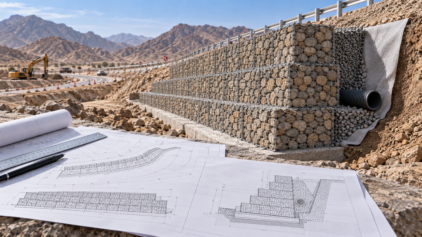
A gabion wall DWG is a CAD drawing that represents the geometry and construction arrangement of a gabion wall. DWG is a common file format used by CAD software for technical drawings. A gabion wall DWG may contain one or more views of the proposed structure. Depending on the project, the drawing can show:
- Plan view
- Elevation
- Cross section
- Gabion unit dimensions
- Wall height
- Base width
- Wall batter
- Foundation
- Backfill
- Geotextile
- Drainage
- Stone fill
- Mesh specification
- Connection details
- Ground levels
The exact information depends on the purpose of the drawing.
Why Gabion Wall CAD Drawings Matter
A technical drawing provides a common reference for the project team. Consultants can use it during design coordination, contractors can use it to understand the construction arrangement, and procurement teams can use it to identify the required products. A clear drawing can reduce uncertainty around:
- Unit sizes
- Wall configuration
- Foundation levels
- Setbacks
- Connections
- Material requirements
- Drainage
- Backfill
For larger projects, the drawing should form part of a coordinated engineering package rather than being used as an isolated product illustration.
What Should a Gabion Wall DWG Include?
The required content varies by project, but a useful technical drawing generally provides enough information to understand the complete wall arrangement.
1. Wall Plan
The plan view shows the horizontal alignment of the wall.
It can identify:
- Wall location
- Wall length
- Curves or changes in alignment
- Corners
- Connections
- Relationship with nearby structures
For roads, developments, drainage channels, and other infrastructure, the plan should be coordinated with the overall site layout.
2. Wall Elevation
The elevation shows the visible face of the gabion wall. It may identify:
- Overall wall height
- Gabion courses
- Unit dimensions
- Stepped arrangement
- Top and bottom levels
- Wall alignment
An elevation helps the construction team understand the final appearance and course arrangement.
3. Gabion Wall Cross Section
The cross section is one of the most important views in a retaining-wall drawing. It can show the relationship between:
Retained soil → filter layer → gabion wall → foundation
A more detailed section may also show:
- Backfill
- Drainage
- Groundwater considerations
- Wall batter
- Foundation treatment
- Toe protection
- Surface drainage
The cross section should reflect the actual design rather than a generic configuration.
Gabion Wall Dimensions in CAD Drawings
Gabion wall dimensions depend on the project requirements. A drawing may identify:
- Basket length
- Basket width
- Basket height
- Wall base width
- Wall top width
- Overall height
- Course height
- Setback
- Foundation depth
- Wall length
These dimensions should be selected according to the design. There is no single gabion wall dimension that is suitable for every application. A landscaping wall, road retaining wall, and wadi protection structure may require completely different configurations.
Gabion Box Dimensions
Gabion boxes are available in different dimensions to suit different construction requirements.
The selected unit size can influence:
- Wall geometry
- Course arrangement
- Stone quantity
- Handling
- Installation
- Final wall profile
The product dimensions should therefore be coordinated with the engineering drawing before procurement. For a large project, the drawing should clearly distinguish between different gabion unit sizes where multiple configurations are required.
Gabion Wall Section Detail
A detailed section should explain how the wall interacts with the ground behind and below it. A typical retaining-wall section may identify:
Gabion Structure
Shows the arrangement of the individual stone-filled units.
Foundation
Shows the prepared base and required foundation level.
Backfill
Shows the retained or engineered material behind the wall.
Filter Layer
Shows the geotextile or other filtration arrangement where specified.
Drainage
Shows how water is managed around the wall.
Ground Levels
Shows existing and finished ground levels.
This information helps the contractor construct the wall according to the intended design.
Gabion Wall Foundation Detail
The foundation should be clearly represented in the drawing. Depending on the project, the foundation detail may show:
- Excavation
- Existing soil
- Prepared subgrade
- Compacted foundation material
- Leveling layer
- Foundation width
- Foundation elevation
The final foundation treatment should be based on the site's geotechnical conditions. A CAD drawing should not be interpreted as proof that the same foundation arrangement is suitable for another location.
Gabion Wall Drainage Detail
Drainage is an important part of retaining-wall design. Although gabion walls are permeable, water movement through and around the structure still needs to be considered.
The drawing may identify:
- Geotextile
- Drainage layer
- Toe drain
- Surface drainage
- Water outlet
- Channel
- Erosion protection
The appropriate arrangement depends on the site's water conditions. For projects near wadis or drainage channels, hydraulic conditions may need to be assessed separately.
Gabion Wall Geotextile Detail
A geotextile filter can be installed behind a gabion wall where the project requires filtration and soil separation. The drawing should make clear:
- Where the geotextile is located
- Which surfaces it covers
- How it terminates
- How it relates to drainage
- How it interacts with backfill
The geotextile specification should be selected according to the soil and hydraulic conditions. It should not be included simply because it appears in a generic gabion detail.
Gabion Wall Mesh Detail
The CAD drawing may also identify the mesh configuration. Important information can include:
- Mesh opening
- Wire diameter
- Mesh type
- Wire coating
- Connection arrangement
- Diaphragm arrangement
This information allows procurement and construction teams to identify the intended product. The drawing should be coordinated with the manufacturer's technical specification.
Gabion Wall Stone Detail
Stone fill is an essential part of the gabion system. A technical drawing or specification may identify:
- Stone type
- Stone size
- Durability
- Appearance
- Fill requirements
The selected stone should be compatible with the mesh opening. For visible architectural gabion walls, stone selection may also affect the final appearance significantly.
Gabion Wall Connection Detail
Individual gabion units need to be connected so that the wall functions as an integrated structure. A detailed drawing may show:
- Horizontal connections
- Vertical connections
- Lacing
- Clips
- Spirals
- Internal connections
- Diaphragms
The connection method should follow the approved product system.
Gabion Wall DWG for Engineers
Engineers may use CAD drawings during several stages of a project.
Preliminary Design
A standard detail can help establish the basic concept.
Design Development
The drawing can be modified to reflect the actual wall dimensions and site conditions.
Tender Documentation
The drawing can communicate the expected construction arrangement to bidders.
Construction Documentation
The approved drawing can form part of the construction package.
As-Built Documentation
The final installed arrangement can be documented for project records.
At every stage, the drawing should be clearly identified as preliminary, approved, or as-built to avoid confusion.
Gabion Wall DWG for Contractors
Contractors need practical information that can be translated into site work. A useful drawing should make it possible to understand:
- Where the wall starts
- Where it ends
- How wide it is
- How high it is
- How the courses are arranged
- What gabion sizes are required
- How the units connect
- Where the filter layer goes
- How backfill is placed
- How drainage is managed
A drawing that only shows a generic basket is not sufficient for complex retaining-wall construction.
Gabion Wall DWG for Saudi Arabia Projects
Saudi projects can involve very different environments and applications. A CAD detail should therefore be adapted to the project's location and requirements.
Riyadh
Inland projects should consider local soil conditions, ground levels, surface drainage, and potential intense rainfall.
Jeddah
Coastal exposure can make corrosion protection an important consideration for wire mesh systems.
Dammam and Jubail
Industrial and coastal environments may require careful material and coating selection.
Taif and Mountainous Areas
Steep terrain can require coordination between retaining walls, slope stabilization, and drainage.
Wadi Projects
Drawings should address water flow, erosion, channel geometry, and appropriate protection systems.
Gabion Wall CAD Drawing vs Construction Drawing
These terms are related but not always identical. A CAD drawing describes the digital format or method used to create the drawing. A construction drawing describes the purpose of the drawing. A DWG file can therefore be a construction drawing, design drawing, detail drawing, or preliminary drawing.
The important question is not simply whether the file is in DWG format. The important question is whether the drawing contains enough accurate information for its intended purpose.
What to Check Before Using a Standard Gabion DWG
Before incorporating a standard CAD detail into a Saudi project, review:
Site Conditions
Does the drawing reflect the actual ground conditions?
Wall Height
Is the proposed configuration suitable for the required height?
Loading
Are roads, vehicles, buildings, equipment, or other surcharge loads present?
Foundation
Does the foundation arrangement suit the soil?
Drainage
Does the drawing address actual water conditions?
Materials
Do the mesh, wire, coating, and stone specifications match the project?
Geometry
Does the wall profile provide the required stability and fit within the available space?
Local Requirements
Does the drawing comply with the project's specifications and applicable requirements?
This review prevents a generic detail from being mistaken for a completed engineering design.
Common Problems With Generic Gabion Wall Drawings
Incorrect Wall Dimensions
A generic drawing may not be suitable for the required wall height or loading.
Missing Drainage Information
The drawing may show the gabion basket but omit the surrounding drainage system.
No Foundation Information
A basket detail without foundation information does not explain how the wall should be supported.
Unclear Material Specifications
A drawing may show the mesh without defining wire or coating requirements.
Missing Ground Levels
Without existing and finished levels, it can be difficult to establish the actual wall geometry.
No Site-Specific Loads
A generic retaining-wall drawing cannot account for project-specific surcharge conditions.
How Gabion Wall Drawings Support Quantity Estimation
A coordinated drawing can help the project team estimate:
- Number of gabion units
- Stone volume
- Mesh requirements
- Connection materials
- Geotextile quantity
- Backfill volume
- Foundation quantities
Accurate quantities depend on the final approved design and project measurements. For large projects, quantities should be calculated from coordinated drawings and specifications rather than from generic product dimensions.
How to Request a Gabion Wall Drawing From a Supplier
When requesting technical drawings, provide as much project information as possible. Useful information includes:
- Project location
- Wall length
- Wall height
- Site levels
- Retained soil information
- Slope geometry
- Loading conditions
- Drainage conditions
- Required gabion type
- Required stone
- Applicable project specifications
This allows the supplier and design team to provide information that is more relevant to the application.
Why Choose Hitech Gabion for Gabion Systems in Saudi Arabia?
Hitech Gabion provides gabion and earth-retention solutions for construction and infrastructure applications across Saudi Arabia. Its solutions support projects involving:
- Gabion retaining walls
- Gabion baskets
- Gabion boxes
- Slope protection
- Erosion control
- Wadi protection
- Reno mattresses
- Infrastructure protection
- Landscaping
For project teams requiring gabion products and technical information, Hitech Gabion can support product selection and project coordination. Any project-specific engineering design should remain the responsibility of the qualified design team and should reflect the actual site conditions.
Frequently Asked Questions